Audio Debug Introduction
1. Audacity Operation
1.1. How to check the signal value
It`s often necessary to check the signal over a period time in the intercom debugging. The method to check the signal value through Audacity is as the figure shown below.
-
Select the time period to be analyzed

-
Open the "Analyze"

-
Find the average amplitude of the selection

1.2. How To Check The Frequency Response Characteristic
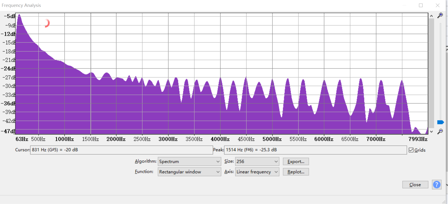
It`s often necessary to adjust the frequency response characteristic in the intercom debugging. The method to check the frequency response characteristics of audio files through Audacity is as the figure shown below. After getting the frequency response curve of the current device, you can adjust it through EQ.
-
Select the data to be analyzed
-
Click "Analyze"

-
Click "Scan Selection"

2. MI Audio Internal Process Introduction
2.1. MI Audio Block Diagram
Note: When MI_AI is version 2.19 and MI_AO is version 2.17, MI does not include algorithm implementation and algorithm concatenation process (including the debug and dump data methods provided by MI before), but the following concatenation algorithm process is still recommended.
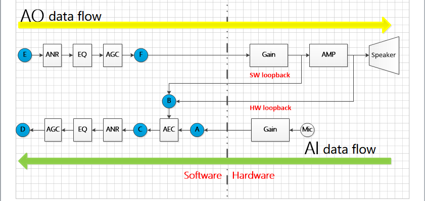
The basic data flow of MI Audio is as shown below:
The following description doesn`t include the basic situation of sound source localization, sound detection, beamforming, resampling, codec and other algorithms.
2.2. AI Data Flow Analysis
The green arrow is represent for AI data flow in picture above.
Microphone data collection ——> Chip internal gain ——> MI layer (A) where the data is the original PCM number ——>sent to the AEC algorithm for processing with data from AO (B) ——> The processed data arrives at C ——> sent it to the APC (which is the collection of ANR, EQ, HPF and AGC) for processing ——>The final data arrives at D
Difference between SW loop back and HW loop back:
The main difference is the AO data that sent back to AEC.
SW loop back is used to process the AO data that has only passed the internal gain of the chip, the advantage is that no external circuit is required for specific voltage division design, and only one audio input channel is occupied.
For the distortion caused by the power amplifier chip of the external circuit, SW loop back cann`t handle better than HW loop back.
HW loop back is used to process the AO data that processed by external circuit power amplifier chip, the above situation can be better dealt with, but a specific voltage divider design is required for the external circuit, one more audio input channel is occupied, and the peak value returned by the loop back cann `t exceed the internal range (3.3V) of the chip. So HW loop back must have two audio input channels before it can be used.
Note: HW loop back can be used by dual-channel Amic.
2.3. AO Data Flow Analysis
The yellow arrow is represent for AO data flow.
The application sends the PCM data to be played through the MI interface (dot E).
the PCM data to be played sent by application through MI (dot E)——> send data to APC (which is the collection of ANR, EQ and AGC) for processing, dot F ——> chip internal gain, external circuit power amplifier ——> speaker output.
2.4. Raw Data And Algorithm Normal Process affirmance
The blue dots data can be dumped through the debug method provided by SDK(It`s only for debugging, if there is a file name error, the SDK will not make corrections temporarily). The dump method provided by SDK needs to specify the file save path and the data location to be dumped by exporting a series of environment variables before being applied.
-
specify the file save path
export MI_AI_DUMP_PATH=xxx, specify the dump path of AI is xxx

export MI_AO_DUMP_PATH=xxx, specify the dump path of AO is xxx
-
specify the data location of dump
-
AI:
Export MI_AI_DUMP_PCM_ENABLE=1, specify the raw pcm of dump AI(the data at dot A). Filename is MI_AI_Dev*Chn*_*K_Src.pcm.
export MI_AI_DUMP_AEC_ENABLE=1, Specify the data before and after dump AI AEC(the data at dots A, B, and C).
Filenames are MI_AI_Dev*Chn*_*K_AiIn, pcm、MI_AI_Dev*Chn*_*K_AoIn.pcm and MI_AI_Dev*Chn*_*K_AecOut.pcm.(When AEC is enabled, the contents of MI_AI_Dev*Chn*_*K_AiIn.pcm and MI_AI_Dev*Chn*_*K_Src.pcm are the same)
Export MI_AI_DUMP_VQE_ENABLE=1, specify the data before and after dump AI APC.(The data at dots C and D), filenames are MI_AI_Dev*Chn*_*K_VqeIn.pcm and MI_AI_Dev*Chn*_*K_VqeOut.pcm (When AEC is enabled, the contents of MI_AI_Dev*Chn*_*K_VqeIn.pcm and MI_AI_Dev*Chn*_*K_AecOut.pcm are the same. When AEC is turned off, the contents of MI_AI_Dev*Chn*_*K_Src.pcm and MI_AI_Dev*Chn*_*K_VqeIn.pcm are the same).
-
AO:
Export MI_AO_DUMP_PCM_ENABLE=1, specify the data that dump will finally send to the driver(the data at dot F), filename is MI_AO_Dev*_*K_Dst.pcm.
Export MI_AO_DUMP_VQE_ENABLE=1,specify the data before and after dump AO APC(the data at dots E and F), filenames are MI_AO_Dev*_*K_VqeIn.pcm and MI_AO_Dev*_*K_VqeOut.pcm. (When only APC is enabled in AO, the contents of MI_AO_Dev*_*K_VqeOut.pcm and MI_AO_Dev*_*K_Dst.pcm are the same.)
* is the device id, channel id and sample rate specific used by application.
Note: Dump the audio files at the required nodes, don`t dump all of them at the same time, otherwise it may cause the file to be written all the time and cause the SDK to drop frames.
-
3. Audio Related Algorithm Introduction
3.1. AEC(Acoustic Echo Cancellation)
3.1.1. AEC Algorithm Introduction
AEC(short for Acoustic Echo Cancellation), used to eliminate the sound emitted by speaker directly or indirectly coupled back to the microphone.
3.1.2. AEC Algorithm Parameter Description
The data structure of setting AEC parameters provided by MI API is as below:
typedef struct

MI_AI_AecConfig_s
{
    MI_BOOL bComfortNoiseEnable;

    MI_S16 s16DelaySample;

    MI_U32 u32AecSupfreq[6];

    MI_U32 u32AecSupIntensity[7];

    MI_S32 s32Reserved;

} MI_AI_AecConfig_t;
The following is the data structure that the AEC algorithm provides to the application to set the AEC parameters:s
typedef struct

{

    IAA_AEC_BOOL comfort_noise_enable;

    short delay_sample;

    unsigned int suppression_mode_freq[6];

    unsigned int suppression_mode_intensity[7];

}AudioAecConfig;
| Parameter | Function | Description |
|---|---|---|
| bComfortNoiseEnable(MI)/comfort_noise_enable(AEC) | AEC adds comfort noise and enable | Set to FALSE by default. Description: When it`s enabled, the processing result of the AEC algorithm will add some background noise, so that the processed sound will not be too hollow. It`s mainly to solve the problem that the AEC is too clean, which causes the ANR to take too long to converge (the specific phenomenon is that the noise between the voices is pulled up and then suppressed) |
| s16DelaySample(MI)/delay_sample(AEC) | Echo delay samples between left and right channels | Set to 0 by default. Description: Due to the placement of the microphone and the speaker, the distance between the microphones, etc., the time points when the left and right channels receive the echo are inconsistent, and the echo delay between the two channels is different. This value indicates how many sampling points the left channel received the echo earlier than the right. Note: This parameter is only applicable to the case of dual-channel AEC, and is not recommended. |
| u32AecSupfreq(MI)/suppression_mode_freq(AEC) | Frequency band processed by AEC | Description: The array divides the highest frequency of the current sampling rate into 8 frequency bands for processing. For the conversion formula of array elements and frequency range, see Formula 1. Assuming the current sampling rate is 16K, take {4, 6, 36, 49, 50,51} as an example, the maximum sampling frequency is 8K, the first frequency band F1 = (0~4) * 8000 /128 = 0 ~250Hz; the second frequency band F2 = (4~6) * 8000/128 = 250~375Hz; the third frequency band F3 = (6~36) * 8000/128 = 375~2250Hz; the Four frequency bands F4 = (36~49) * 8000/128 = 2250~3062Hz, the fifth frequency band F5 = (49~50) * 8000/128 = 3062~3125Hz; the sixth frequency band F6 = (50~51) * 8000/128 = 3125~3187Hz; the seventh frequency band F7 = (51~128) * 8000 /128= 3187~8000Hz. Note: The array requires that each element must be bigger than the previous one. Parameter range: [1,127] |
| u32AecSupIntensity(MI)/suppression_mode_intensity(AEC) | Intensity processed by AEC | Description: The array represents the echo cancellation intensity of the frequency band, and each element corresponds to the frequency range divided by u32AecSupfreq. Note: Parameter range: [0,15], The greater the intensity, the more details are eliminated and the more unnatural the sound. Conversely, the smaller the intensity, the more details are retained, but the echo cancellation is not clean enough.(If the elimination effect is not satisfied, please decide how to adjust it by yourself.) |
Formula 1:
3.2. ANR(Acoustic Noise Reduction)
3.2.1. ANR Related Algorithm Introduction
ANR(short for Acoustic Noise Reduction), used to eliminate the continuous noise in the environment (such as white noise, etc.), which cann`t handle the sudden noise well.
3.2.2. ANR Algorithm Parameter Description
The data structure of setting ANR parameters provided by MI API is as below.
As the NR algorithm has been updated, please follow the NR data structure corresponding to the current SDK version.
typedef struct

MI_AUDIO_AnrConfig_s
{
    MI_AUDIO_AlgorithmMode_e eMode;

    MI_U32   u32NrIntensity;

    MI_U32   u32NrSmoothLevel;

    MI_AUDIO_NrSpeed_e eNrSpeed;

}MI_AUDIO_AnrConfig_t;
| Parameter | Function | Description |
|---|---|---|
| eMode | ANR algorithm mode | Description: The parameter represents the mode of the ANR algorithm, and different modes correspond to different application scenarios. E_MI_AUDIO_ALGORITHM_MODE_DEFAULT: Audio mode, which can use the default noise reduction parameters set in the algorithm for audio data. E_MI_AUDIO_ALGORITHM_MODE_USER: The mode all uses the noise reduction parameters under the application. E_MI_AUDIO_ALGORITHM_MODE_MUSIC: Music mode, which can use the noise reduction parameters set in the algorithm for music data. (Recommended to use) |
| u32NrIntensity | ANR algorithm intensity | Recommended value: 20 Description: The parameter represents the intensity of ANR algorithm. The larger the value, the better the noise reduction effect, but the more detail loss. Conversely, the smaller the value, the more details are retained, but the noise cann`t be removed cleanly. (Needs to be weighed and fine-tuned) Note: Parameter range: [0,30]. |
| u32NrSmoothLevel | ANR algorithm smooth level. | Recommended value: 10 Description: The parameter represents the smooth level processed by ANR algorithm. The larger the value, the smoother the noise reduction effect, the smoother the effect, the less detail loss in the frequency domain. Note: parameter range: [0,10]. |
| eNrSpeed | ANR algorithm convergence speed | Recommended value: E_MI_AUDIO_NR_SPEED_MID Description: The parameter represents the convergence speed of ANR algorithm. The faster the convergence, the more details are lost. Conversely, the slower the convergence speed, the longer the reference time, the more details are retained, but it will also extend the time for noise reduction to work. When the convergence speed has been set to E_MI_AUDIO_NR_SPEED_HIGH, but it still converges slowly, you can enable the bComfortNoiseEnable of AEC to make the AEC processing result actively add noise to assist the ANR convergence. |
typedef struct MI_AUDIO_AnrConfig_s

{
    MI_AUDIO_AlgorithmMode_e eMode;

    MI_U32   u32NrIntensityBand[_NR_BAND_NUM - 1];

    MI_U32   u32NrIntensity[_NR_BAND_NUM];

    MI_U32   u32NrSmoothLevel;

    MI_AUDIO_NrSpeed_e eNrSpeed;

}MI_AUDIO_AnrConfig_t;
The following is the data structure provided by the ANR algorithm for the application to set the ANR parameters (Effect related part):
typedef struct{

    unsigned int anr_enable;

    unsigned int user_mode;

    int anr_intensity_band[_NR_BAND_NUM-1];

    int anr_intensity[_NR_BAND_NUM];

    unsigned int anr_smooth_level;

    NR_CONVERGE_SPEED anr_converge_speed;

}AudioAnrConfig;
| Parameter | Function | Description |
|---|---|---|
| eMode(MI)/user_mode(ANR) | ANR algorithm mode | Description: The parameter represents the mode of ANR algorithm. Different modes correspond to different application scenarios. E_MI_AUDIO_ALGORITHM_MODE_DEFAULT(MI)/0(ANR): Audio mode, which can use the default noise reduction parameters set in the algorithm for audio data. E_MI_AUDIO_ALGORITHM_MODE_USER(MI)/1(ANR): The mode all uses the noise reduction parameters under the application. E_MI_AUDIO_ALGORITHM_MODE_MUSIC(MI)/2(ANR): Music mode, which can use the noise reduction parameters set in the algorithm for music data. (Recommended to use) |
| u32NrIntensityBand(MI)/anr_intensity_band(ANR) | ANR frequency band division | Description: Use u32NrIntensityBand(MI)/anr_intensity_band(ANR) with u32NrIntensity, same as AEC's u32AecSupfreq and u32AecSupIntensity, which can divide the entire frequency band into 7 segments to make different noise reduction intensities act on different frequency bands. |
| u32NrIntensity(MI)/anr_intensity(ANR) | ANR algorithm intensity | Recommended value: 20 Description: The parameter represents the intensity of ANR algorithm. The larger the value, the better the noise reduction effect, but the more detail loss. Conversely, the smaller the value, the more details are retained, but the noise cann`t be removed cleanly. (Needs to be weighed and fine-tuned) Note: Parameter range: [0,30]. |
| u32NrSmoothLevel(MI)/anr_smooth_level(ANR) | ANR algorithm smooth level. | Recommended value: 10 Description: The parameter represents the smooth level processed by ANR algorithm. The larger the value, the smoother the noise reduction effect, the smoother the effect, the less detail loss in the frequency domain. Note: parameter range: [0,10]. |
| ENrSpeed(MI)/anr_converge_speed(ANR) | ANR algorithm convergence speed | Recommended value: E_MI_AUDIO_NR_SPEED_MID(MI)/1(ANR) Description: The parameter represents the convergence speed of ANR algorithm. The faster the convergence, the more details are lost. Conversely, the slower the convergence speed, the longer the reference time, the more details are retained, but it will also extend the time for noise reduction to work. When the convergence speed has been set to E_MI_AUDIO_NR_SPEED_HIGH(MI)/2(ANR), but it still converges slowly, you can enable the bComfortNoiseEnable(MI)/comfort_noise_enable(AEC) of AEC to make the AEC processing result actively add noise to assist the ANR convergence. |
3.3. EQ(Equalizer)
3.3.1. EQ Related Algorithm Introduction
EQ(short for Equalizer), which is used to increase or decrease the energy of some frequency bands.
3.3.2. EQ Algorithm Parameter Introduction
The data structure of setting EQ parameters provided by MI API is as below:
typedef struct MI_AUDIO_EqConfig_s

{
    MI_AUDIO_AlgorithmMode_e eMode;

    MI_S16     s16EqGainDb[129];

}MI_AUDIO_EqConfig_t;
The following is the data structure provided by the EQ algorithm for the application to set the EQ parameters (Effect related part):
typedef struct{

    unsigned int eq_enable;

    unsigned int user_mode;

    short eq_gain_db[_EQ_BAND_NUM];

}AudioEqConfig;
| Parameter | Function | Description |
|---|---|---|
| eMode (MI)/user_mode(EQ) | EQ algorithm mode | Description: The parameter represents the mode of EQ algorithm. E_MI_AUDIO_ALGORITHM_MODE_DEFAULT(MI)/0(EQ): default mode, regardless of the application parameters, and amplify the full frequency band. E_MI_AUDIO_ALGORITHM_MODE_USER(MI)/1(EQ): The mode all uses the noise reduction parameters under the application. (Use this mode when you need to adjust by yourself) |
| s16EqGainDb(MI)/eq_gain_db(EQ) | EQ algorithm array | Description: It represents the gain setting of each frequency band. This parameter divides the maximum sampling frequency corresponding to the current sampling rate into 129 parts, which can individually adjust the energy of a certain frequency band. Assuming that the current sampling rate is 16K, the maximum sampling frequency is 8K, and the frequency band corresponding to each one is F = 8000/129 ≈ 62Hz. The frequency bands corresponding to this array element are 0~62Hz, 62~124Hz, 124~192Hz,……, 7938~8000Hz. Note: parameter range: [-50,20]dB. When the gain to be adjusted changes greatly, it is often impossible to complete the change in one frequency band. So it is necessary to set the adjacent frequency band to the same parameter to achieve the purpose. |
3.4. AGC(Automatic Gain Control)
3.4.1. AGC Related Algorithm Introduction
AGC(short for Automatic Gain Control), which can perform gain control on the input data. Gain when the signal is too small, and attenuate when it is too large.
3.4.2. AGC Algorithm Parameter Introduction
The data structure of setting AGC parameters provided by MI API is as below:
As the AGC algorithm has been updated, the data structure will be changed.
typedef struct AgcGainInfo_s{
    MI_S32   s32GainMax;
    MI_S32   s32GainMin;
    MI_S32   s32GainInit;
}AgcGainInfo_t;

typedef struct MI_AUDIO_AgcConfig_s
{
    MI_AUDIO_AlgorithmMode_e eMode;
    AgcGainInfo_t stAgcGainInfo;
    MI_U32     u32DropGainMax;
    MI_U32     u32AttackTime;
    MI_U32     u32ReleaseTime;
    MI_S16     s16Compression_ratio_input[5/7];
    MI_S16     s16Compression_ratio_output[5/7];
    MI_S32     s32TargetLevelDb/s32DropGainThreshold
    MI_S32     s32NoiseGateDb;
    MI_U32     u32NoiseGateAttenuationDb;
}MI_AUDIO_AgcConfig_t;
The following is the data structure provided by the AGC algorithm for the application to set the AGC parameters (Effect related part):
typedef struct

{

    int gain_max;

    int gain_min;

    int gain_init;

}AgcGainInfo;


typedef struct

{

    unsigned int agc_enable;

    unsigned int user_mode;

    AgcGainInfo gain_info;

    unsigned int drop_gain_max;

    unsigned int attack_time;

    unsigned int release_time;

    short compression_ratio_input[_AGC_BAND_NUM];

    short compression_ratio_output[_AGC_BAND_NUM];

    int drop_gain_threshold;

    int noise_gate_db;

unsigned int noise_gate_attenuation_db;

unsigned int gain_step;  //Supported by new algorithm version

}AudioAgcConfig;
| Parameter | Function | Description |
|---|---|---|
| eMode(MI)/user_mode(AGC) | AGC algorithm mode | Description: The parameter represents the mode of AGC algorithm. Different mode correspond to different application scenarios. E_MI_AUDIO_ALGORITHM_MODE_DEFAULT(MI)/0(AGC): Audio mode, which can use the AGC parameters set in the algorithm for audio data. E_MI_AUDIO_ALGORITHM_MODE_USER(MI)/1(AGC): The mode all uses the noise reduction parameters under the application. (Use this mode when you need to adjust by yourself) E_MI_AUDIO_ALGORITHM_MODE_MUSIC(MI)/2(AGC):Music mode, which can use the AGC parameters set in the algorithm for music data. |
| s32GainMax(MI)/gain_max(AGC) | AGC algorithm adjusts the maximum value of gain(dB) | Description: The parameter is the maximum adjustable gain of the AGC algorithm. Note: Parameter range: [0,60]dB. |
| s32GainMin(MI)/gain_min(AGC) | AGC algorithm adjusts the minimum value of gain(dB) | Description: The parameter is the minimum adjustable gain of the AGC algorithm. Note: Parameter range: [-20,30]dB. |
| s32GainInit(MI)/gain_init(AGC) | AGC algorithm adjusts the initial value of the gain(dB) | Description: The parameter is the initial value adjustable gain of the AGC algorithm. Note: Parameter range: [-20,60]dB. |
| u32DropGainMax(MI)/drop_gain_max(MI) | The maximum value of AGC algorithm gain drop(dB) | Description: It is the maximum value that can be dropped when the AGC algorithm gain adjustment exceeds the target value (s32TargetLevelDb/s32DropGainThreshold(MI)/drop_gain_threshold(AGC) to prevent output saturation.(When the above situation occurs, the AGC algorithm will attenuate in the range of 0dB~u32DropGainMax(MI)/drop_gain_max(AGC) dB, and the adjusted gain will also be limited by stAgcGainInfo(MI)/gain_info(AGC)) Note: Parameter range: \0,60]dB. If the value is set too small and the input signal is much higher than the target value, the gain cann`t be quickly reduced, resulting in peak clipping. If the value is set too large, when the input signal is much higher than the target value s32TargetLevelDb/s32DropGainThreshold(MI)/drop_gain_max(AGC), the gain of the signal will drop too much instantaneously, resulting the frame to be unable to connect, and there may be a clear poop-poop. |
| u32AttackTime(MI)/attack_time(AGC) | AGC algorithm gain drop time | Description: It is the drop time of AGC algorithm gain. (0.5dB down within the set time unit) Time unit: 16ms. The smaller the value, the faster the gain decreases. Set this value as small as possible, otherwise when the input signal is higher than the target value s32TargetLevelDb/s32DropGainThreshold(MI)/drop_gain_max(AGC), it will not drop down quickly. It mainly works with the curve. Note: value range: [1,20] |
| u32ReleaseTime(MI)/release_time(AGC) | AGC algorithm gain rise time | Description: It is the rise time of AGC algorithm gain. (0.5dB down within the set time unit) Time unit: 16ms. The smaller the value, the faster the gain increases. Avoid setting it too small, otherwise, after a long period of gain accumulation, a large input signal suddenly appears, which will cause the sound to burst. Setting it too large will cause the signal pull up failure. It mainly works with the curve. Value range: [1,20] |
| s16Compression_ratio_input(MI)/compression_ratio_input(AGC) s16Compression_ratio_output(MI)/compression_ratio_output(AGC) | AGC algorithm gain setting curve | Description: A gain adjustment curve with 4/6 section slope composed of s16Compression_ratio_input(MI)/compression_ratio_input(AGC) and s16Compression_ratio_output(MI)/compression_ratio_output(AGC). Note: parameter range of the two array elements is [-80,0]dBFS. It is recommended to set the maximum value of compression ratio output to -3dBFS and below to avoid peak clipping. Note: The compression ratio output setting only increases the number of segments that can be adjusted. |
| s32TargetLevelDb/s32DropGainThreshold(MI)/ drop_gain_threshold(AGC) | AGC algorithm gain target value | Description: It is the maximum allowable output gain of the AGC algorithm. When a value is greater than it, the algorithm will attenuate the signal to prevent sound explosion. Note: Parameter range: [-80,0]dB. |
| s32NoiseGateDb(MI)/ noise_gate_db(AGC) | Noise threshold processed by AGC algorithm | Recommended value: -80 Description: It is the noise threshold processed by AGC algorithm. The gain of the input signal below this value is considered as noise by AGC, and the setting of u32NoiseGateAttenuationDb(MI)/ noise_gate_attenuation_db(AGC) is used to attenuate the noise. If you want to keep the noise, set the value to -80, and set the slope of the curve from -80dBFS to the measured noise threshold to 1. It is recommended to use curves to deal with noise. Note: parameter range: [-80,0]dBFS. When the echo from speaker which cann`t processed by opposite side, we can use s32NoiseGateDb(MI)/ noise_gate_db(AGC) and u32NoiseGateAttenuationDb(MI)/ noise_gate_attenuation_db(AGC) together to eliminate it, but it will affect the human voice.(It needs to be weighed) |
| u32NoiseGateAttenuationDb(MI)/ noise_gate_attenuation_db(AGC) | Noise attenuation value processed by AGC algorithm | Recommended value: 0 Description: The gain of noise attenuation processed by the AGC algorithm, which will cooperate with s32NoiseGateDb to deal with noise below the threshold. It is not recommended to use it to attenuate the noise to avoid the output signal from sounding interrupted. Using this value will cause the beginning and end to be eliminated, making the sound unnatural. Note: parameter value: [0,100]dB |
| gain_step | Rate at which gain is applied | Rate at which gain is applied, take 0.5dB as a unit. If it is set to 1, ±0.5dB will be applied for each frame according to requirements. The higher the value is set, the faster the rate of raising and lowering the volume. Range [1, 10]; step size 1 |
Compression ratio input and Compression ratio output need to be set according to the actual scene.(Each product has different devices, structures, and adapted models, and needs to be analyzed by specific audio files)
Take the following as an example:
Compression ratio input = {-80,-60,-40,-20,0};
Compression ratio output = {-80,-60,-30,-15,-10};
As shown in the figure below, the input gain -80~0dB is divided into four slopes:
Keep the original gain within -80dB~-60dB, slope: 1; output gain: -80~-60dB;
Increase the gain slightly within -60dB~-40dB, slope: 1.5; output gain: -60~-30dB;
-40dB~-20dB, slope: 1.25; output gain: -30~-15dB;
-20dB~0dB, slope: 0.25; output gain: -15~-10dB.
Set Compression ratio input and Compression ratio output according to the required curve turning point, fill in the unnecessary part of the array with 0.
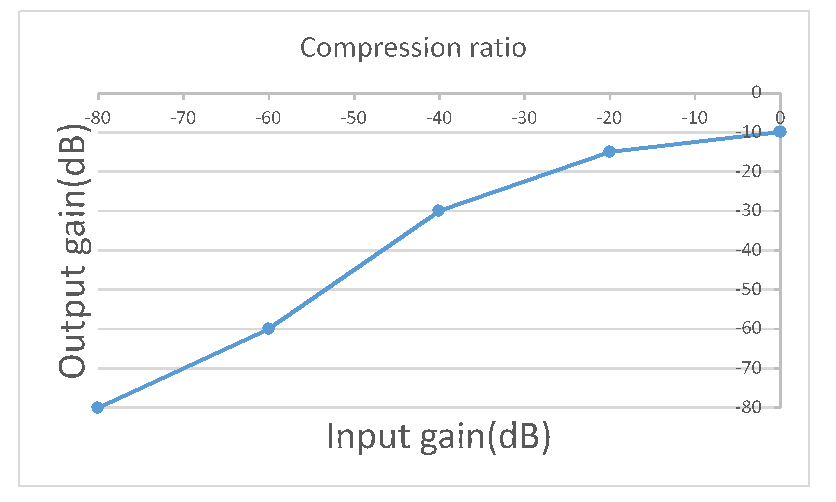
Note: The figure above only explains the parameters and meaning of the curve, and has no actual reference value.
4. Device structure test
It is mainly confirmed by the following two points:
-
Internal isolation
-
Echo Return Loss (ERL)
If these cannot be met, it means that the structural design is not up to standard. Either recommend to modify the structure or reduce the requirements for the effect.
Note: confirm whether the HW loop back or SW loop back are used first; If HW loopback is used, chn1 should be attenuated (-6, -3, 0dB) to ensure that chn0 will not cause distortion due to chn1. All the following steps are performed without enabling any audio algorithms.
4.1. Test Audio File Introduction
Test audio file:
TestFile1 is a piece of noise, used to help confirm the gain of the microphone and speaker.
TestFile2 is a dialogue for foreigners, with a relatively complete frequency band, and the difficulty of elimination is higher than TestFile4. It is used to adjust AEC parameters.
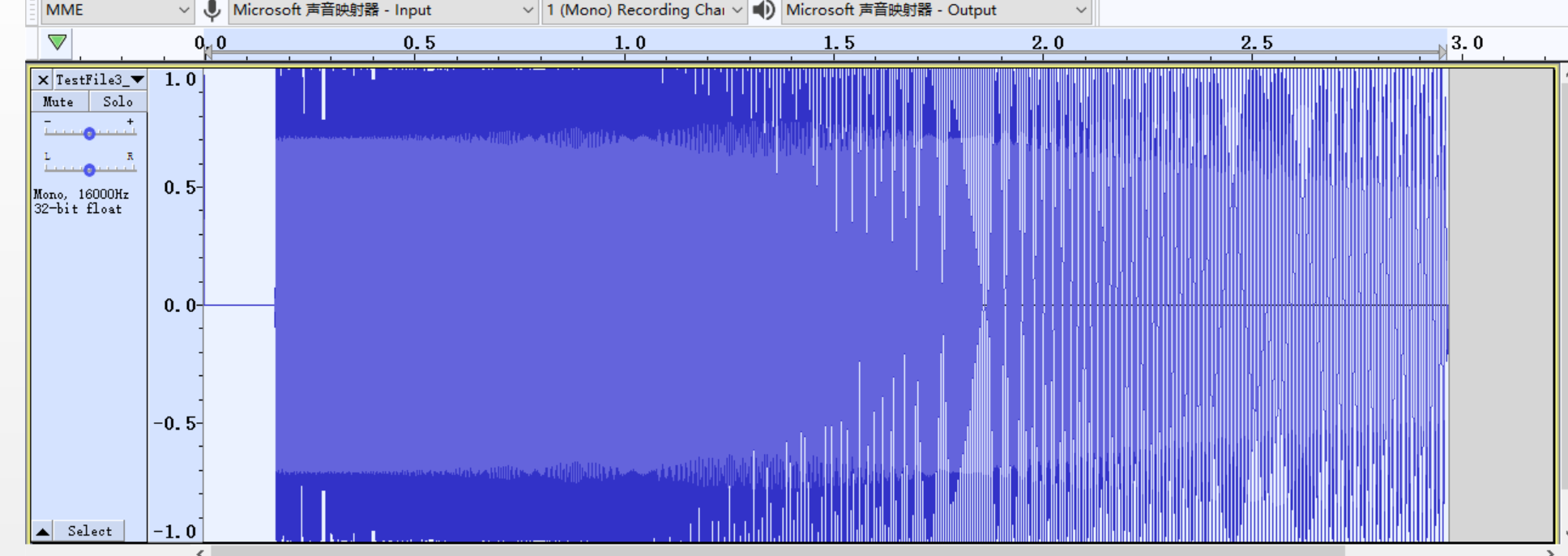
TestFile3 is a sound with a gradually increasing frequency, which is used to sweep the frequency and check the frequency response characteristics of mic and speaker.
TestFile4 is a dialogue for Chinese used to adjust AEC parameters.
4.2. Confirm The Gain Of Speaker And Microphone
The internal isolation and echo return loss need to be measured to confirm the gain of speaker and microphone.
First, determine the gain of the microphone and speaker by measuring according to the user's needs (mic distance and speaker volume). It is the most important step in subsequent tuning. If the user needs to change them, all algorithm related parameters need to be re-adjusted.
4.2.1. Confirm The Gain Of Speaker
-
Find a place where the ambient noise is below 40dbA.
-
Play TestFile1 with the device under test, adjust the gain of speaker, and make it meet the user's needs without distortion.
4.2.2. Confirm The Gain Of Microphone
-
Find a place where the ambient noise is below 40dbA.
-
Place the decibel meter and the device under test together, where a player is one meter away from , use the player to play TestFile1, and adjust the gain to make the decibel meter reaches 70dbA. (If there are no player and device under test , please refer to 4.
-
Use the device under test for reception, dump the data at point A (or the final data recorded by demo without using any algorithm), and adjust the microphone gain to make the RMS reach -25 DBRMS or above. (How to check the signal value)
-
After confirming the speaker and microphone gain, the device under test uses the gain obtained from Confirm The Gain Of Speaker to play TestFile2, and use the adjusted microphone gain to record audio file, confirm distortion or not. If so, please reduce the gain of speaker or microphone. Sometimes because of factors such as structure, speaker or power amplifier, etc. No matter how you adjust it, there will be distortion in some frequency bands. What you can do is to analyze the causes and adjust it as much as possible.
-
If the structural design is not up to standard or the sensitivity of the microphone selection is too low to reach -25 DBRMS, adjust the gain of the microphone to be large enough if the echo recorded by the microphone is not popping after the AEC is enable.
4.3. Internal Isolation
The greater the internal isolation, the better, at least greater than 6dB. The following are the steps to measure internal isolation:
-
Find a place where the ambient noise is below 40dbA.
-
Record and broadcast TesFile1 with the device under test.(Dump the data at point A, or use the data that demo recorded when all algorithm are disable), check the average RMS amplitude and record it as AVGRMS1.
-
Use clay to block the microphone hole on the case, record and broadcast TesFile1 with the device under test.(Dump the data at point A, or use the data that demo recorded when all algorithm are disable), check the average RMS amplitude and record it as AVGRMS2.
-
The internal isolation is AVGRMS1-AVGRMS2.
4.4. Echo Return Loss
The greater the echo return loss, the better, at least make sure it is a positive value. The following are the steps to measure the echo return loss:
-
Find a place where the ambient noise is below 40dbA.
-
Check the average RMS amplitude of TestFile1 and record it as AVGRMS1.
-
Record and broadcast TesFile1 with a device under test.(Dump the data at point A, or use the data that demo recorded when all algorithm are disable), check the average RMS amplitude and record it as AVGRMS2.
-
ERL = AVGRMS1 - AVGRMS2.
-
Set the gain of microphone and speaker to 0dB.(Note: The gain of speaker includes power amplifier gain, if it is amplified, the gain of AO will be set to attenuate to make the overall close to 0dB), replace TestFile1 with TestFile3, record while broadcasting by itself and dump the file.(Dump the data at point A, or use the data that demo recorded when all algorithm are disable)
-
Make sure that the audio file cannot be distorted in any frequency band.
4.5. Frequency response characteristics
How to roughly confirm the quality of the device's frequency response characteristics? How to analyze the causes of poor frequency response characteristics? The steps are as follows:
-
Find a place where the ambient noise is below 40dbA.
-
Set the gain of microphone and speaker to 0dB.(Note: The gain of speaker includes power amplifier gain, if it is amplified, the gain of AO will be set to attenuate to make the overall close to 0dB), record while broadcasting TestFile3 by itself.
If the frequency response characteristics of the reception file are relatively poor, you can follow the steps below to confirm the problem:
-
First disassemble the case to confirm whether the mic and speaker are firmly fixed, if not, reinforce it, repeat the sweep operation, and test whether it becomes better.
-
Use high-fidelity speakers to play TestFile3, make the standard microphone and the device's mic to pick up at the same time and compare to confirm whether the cause is the frequency response characteristic of the microphone (due to the high integration of the mic, the general frequency response characteristic is good)
-
Take the speaker out of the case and repeat the sweep operation. If it becomes better, it is determined to be a device structure problem.
-
Take the speaker out of the case and use the standard microphone (or the mic with no problem) repeat the sweep operation. If only a small part of the frequency band is distorted, use the EQ of AO to repair it after confirming the gain.
-
Take the speaker out of the case and use the standard microphone (or the mic with no problem) repeat the sweep operation. If the full band is distorted as figure shown below, try to reduce the gain of speaker, while it dropped to a very low level but still the same as before, please ask the hardware engineer to help confirm whether there is a problem with the power amplifier circuit design. It’s best to modify the circuit to solve it, otherwise, keep reducing the gain of speaker, self recording and broadcasting and sweeping to find a greatest and undistorted gain(It can be confirmed by measuring the output waveform of the power amplifier with an oscilloscope. This method is more accurate, but it requires to remove the case of device and the assistance of hardware engineer), as it to be the greatest output gain. Use the AGC of AO to increase the output signal and limit it to below -3~-1dB while the speaker sound on that gain doesn’t meet your need.

4.6. Summary
4.6.1. Test Steps
-
Disable the user app first;
-
Enter the dump data command on the console;
export MI_AI_DUMP_PATH=XXX(PATH);

export MI_AI_DUMP_AEC_ENABLE=1;
-
Execute the commands;
./prog_audio_all_test_case -t 20 -I -o /tmp/ -d 0 -m 0 -c 1 -s 8000 -v 15(analog gain)_3(digital gain)-b -O -D 0 -V 0 (speaker gain) -i (wav file path)
Note: for specific gain, please refer to the settings of specific models;
-
Save the audio file generated under XXX(PATH);
-
Use clay to block the mic radio hole on the surface of the device, repeat steps 3 and 4;
-
Compare and analyze two audio files.
4.6.2. Result Analysis
The frequency sweep test is a self-broadcast and self-recorded process. The frequency sweep results of a company's products are shown below. The bottom one is the original sweep audio file, and the top one is the audio file broadcast by the speaker and recovered by the mic. It can be seen that there is a big difference between the two, which shows that there is greater distortion.

4.6.3. Solution
If the frequency sweep result is distorted, take the speaker out of the device case and perform a frequency sweep test again to determine whether the problem is the structure or the speaker.
If it is a structural problem, please block the speaker and mic carefully; if it is a speaker problem, please replace a speaker with good performance. The obvious distortion of the speaker is usually caused by excessive gain, which can be solved by reducing the gain of AO.
5. Sound Effect Adjustment
When the gain of microphone and speaker are confirmed, and the frequency response characteristics have no problem, the sound effect can be adjusted.
5.1. Confirm The Gain Of Speaker And Microphone
In Confirm The Gain Of Microphone, the structural design is not up to standard or the sensitivity of the microphone selection is too low, etc, so the gain cann`t reach-25DBRMS, please follow the steps below:
-
Find a place where the ambient noise is below 40dbA.
-
Set the gain of microphone and speaker to 0dB. Note: The gain of speaker includes power amplifier gain, if it is amplified, the gain of AO will be set to attenuate to make the overall close to 0dB.
-
Play the TestFile3, self-record and self-broadcast(Dump the data at point A, or use the data that demo recorded when all algorithm are disable), and then confirm that the recorded amplitude is relatively small.(The following will explain the processing of frequency band distortion)
-
Play the TestFile2, self-record and self-broadcast, adjust the microphone gain to the maximum without distortion.(Dump the data at point A, or use the data that demo recorded when all algorithm are disable)
-
Adjust the speaker to the gain that meets the requirements. After adjusting the speaker, the microphone should also be adjusted together. Generally follow the principle: plus one minus one, that is, speaker plus 1dB, and microphone correspondingly minus 1dB.
In step 4, due to the structural design is not up to standard, the mic will be distorted with a small gain, or under the premise of ensuring no distortion, the amplitude of the sound output by the mic is very small, please try the following steps to adjust:
When the microphone gain is very small, there is distortion. According to Internal Isolation to confirm whether the device structure up to standard.
While there is a problem with device structure you don`t wanna modify, just decrease the gain of speaker and go on the step Confirm The Gain Of Speaker And Microphone to confirm the new gain of microphone, or try to eliminate this distortion by adjusting the speaker, the steps are as follows:
-
Find a place where the ambient noise is below 40dbA.
-
Set the gain of the microphone and speaker to the current gain.
-
Play the TestFile3, self-record and self-broadcast(Dump the data at point A, or use the data that demo recorded when all algorithm are disable). Check and find distortion, apply frequency analysis to find out the frequency bands with higher gain than others, and attenuate these by setting AO`s EQ(How to adjust the EQ parameters of AO?. It is not suitable for distortion caused by resonance), repeat steps 1 and 2, if there is still distortion after adjusting the EQ for these frequency bands, you can only increase the attenuation value and continue trying.
When the speaker uses EQ to correct its frequency response, but it has little effect.You can consider reducing the gain of the microphone, enable the ANR and AGC of the microphone to adjust the data, find the echo that cannot be eliminated in the AEC processed data, and use ANR and AGC to attenuate.
When the microphone data obtained by the above operation is still very quiet, try to increase the microphone gain to make the echo burst, and at the same time increase the intensity of AEC's echo cancellation processing.(Or suggest changing to one-way intercom) (Use SW loopback instead of HW loopback)
5.2. Adjust the EQ parameters of AO and modify the speaker's frequency response characteristics
Only when the speaker's frequency response characteristics are very poor, or some fixed-frequency echoes cannot be eliminated, use the EQ of AO.
How to get the adjustment table of AO EQ?
When only a small part of the specific frequency band will be distorted, you can confirm it directly through the audio file dumped, and then fill in the appropriate attenuation directly on the AO EQ table to correct it.
But when the recorded audio files have poor frequency response characteristics (not recommended when the distortion is caused by frequency multiplication), you can consider the following methods to adjust the AO EQ table. (Based on the current AI/AO gain)
-
Import data in Audacity, self-record and self-broadcast TestFile3, import the recorded data and the original audio file played; adjust them to ensure that the data is aligned on the time axis.

-
Open the frequency analysis of the above audio files to get the frequency response characteristic curve data.
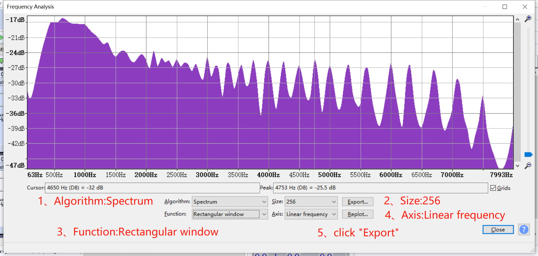
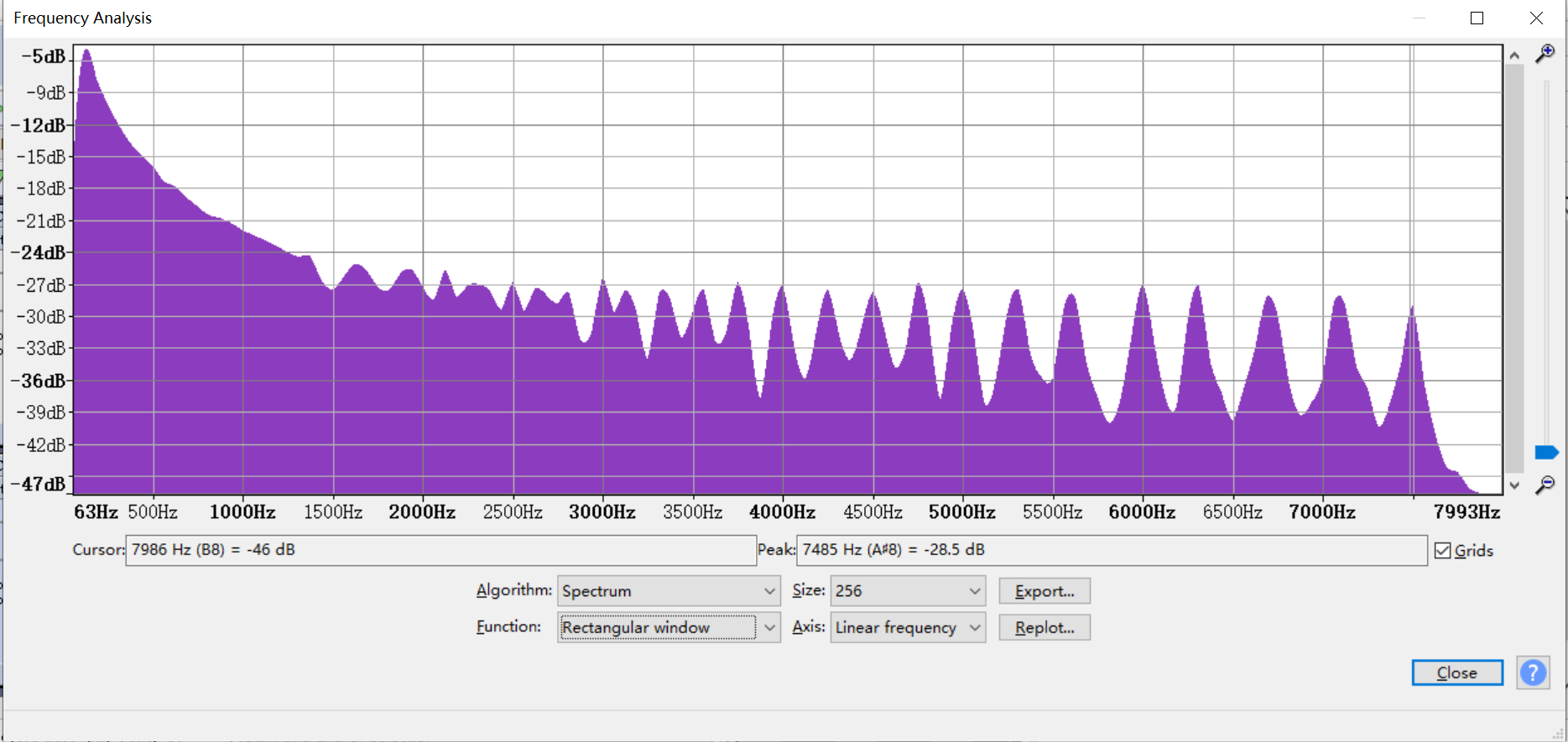
-
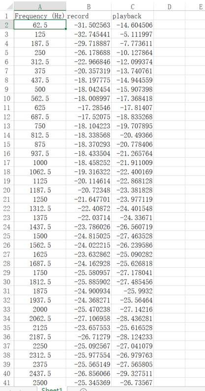
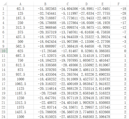
Open Excel and enter the curve data exported above.
-
Count the difference between the gain value of the recorded audio file and the playback audio file in each frequency band, and the average value of the gain difference.
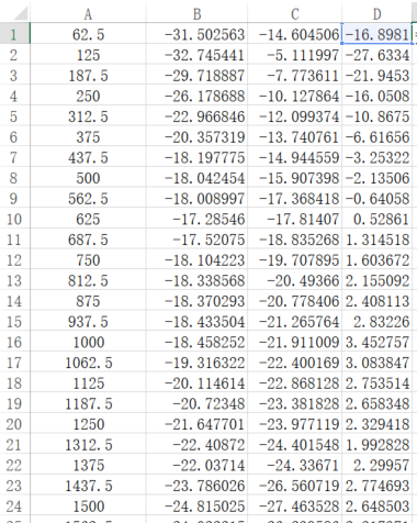
The average of the difference gain value is 0.142025dB.
-
Subtract the average values from the difference gain values.

-
Excluding the excessively large value, convert it to an integer and fill it in the AO EQ table.
As shown in column F.
5.3. AEC Frequency Band And Intensity Adjustment
After confirmed the gain of speaker and microphone, adjust the AEC frequency band and intensity.
-
Set the frequency band division and intensity of AEC to the following parameters, and perform one-way intercom (self-record and self-broadcast TestFile2 for simulation).
u32AecSupfreq[6] = {20,40,60,80,100,120}; // MI
u32AecSupIntensity[7] = {4,4,4,4,4,4,4}; // MI
suppression_mode_freq[6] = {20,40,60,80,100,120}; // AEC
suppression_mode_intensity[7] = {4,4,4,4,4,4,4}; // AEC
-
Dump the file processed by AEC, check whether there is echo left in the file, find the corresponding frequency band, divide it, adjust the frequency range of echo into one, set it to the u32AecSupfreq(MI)/ suppression_mode_freq(AEC) array, and adjust the u32AecSupIntensity(MI)/ suppression_mode_intensity(AEC) array at the same time to enhance the elimination of this frequency band echo intensity.
-
When the AEC processed audio file obtained from dump has data that has been deleted by mistake, you can put AecAiIn, AecAoIn, and AecOut in Adobe audition for comparison to see if there is a brighter part of the deleted frequency band, if not, adjust the u32AecSupIntensity(MI)/ suppression_mode_intensity(AEC) array , and reduce the AEC cancellation intensity of this frequency band.
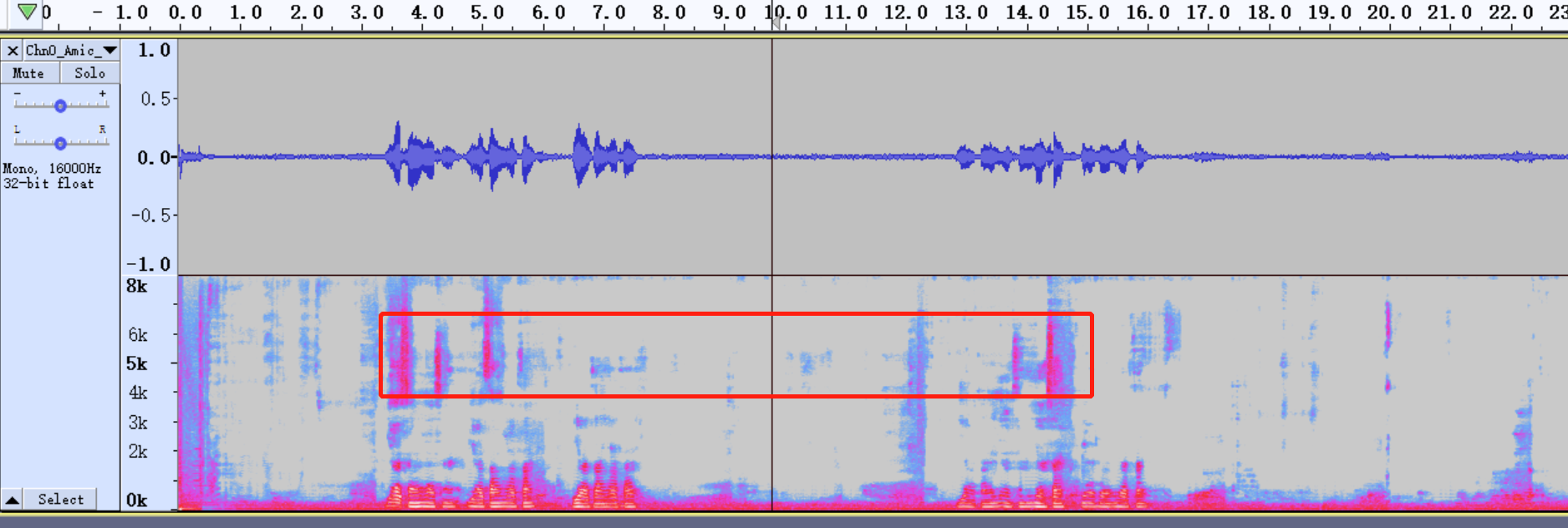
Example: As shown in the figure below, through the audio file AecOut (playing the audio file, viewing the frequency spectrum), we find that there is still echo uncancelled at 4K~7K. Divide it into multiple AEC cancellation segments and adjust the AEC cancellation intensity. 4000/62.5=64, 7000/62.5=112, so we can adjust the AEC parameters as follows:
u32AecSupfreq[6] = {20,40,64,90,112,120}; // MI u32AecSupIntensity[7] = {4,4,4,6,6,4,4};
u32AecSupfreq[6] = {20,40,64,90,112,120}; // AEC u32AecSupIntensity[7] = {4,4,4,6,6,4,4};
(The elimination intensity of AEC needs to be set according to the actual situation)
Note: When the echo of some fixed frequency bands cannot be eliminated, the EQ of the mic can be used for attenuation to eliminate these echoes.
5.4. ANR parameter adjustment
ANR can be used to reduce noise for recorded sound which have continuous noise due to environmental or hardware problems, but ANR cannot handle the sudden noise. Do not speak before testing, let it receive a tone as a reference.
-
Set the default of ANR as follow, only enable AEC and ANR in Vqe setting, get the files before and after APC algorithm.
eMode = E_MI_AUDIO_ALGORITHM_MODE_MUSIC;  // MI
u32NrIntensity = 20;
u32NrSmoothLevel = 10;
eNrSpeed = E_MI_AUDIO_NR_SPEED_MID;
Or
eMode = E_MI_AUDIO_ALGORITHM_MODE_MUSIC;  // MI
u32NrIntensityBand[6] = {20,40,60,80,100,120};
u32NrIntensity[7] = {20,20,20,20,20,20,20};
u32NrSmoothLevel = 10;
eNrSpeed = E_MI_AUDIO_NR_SPEED_MID;

user_mode= 2;  // ANR
anr_intensity_band [6] = {20,40,60,80,100,120};
anr_intensity [7] = {20,20,20,20,20,20,20};
anr_smooth_level= 10;
anr_converge_speed= 1;
-
Check the file processed by the APC algorithm.
-
The convergence time of the ANR algorithm is too long (the time for the noise in the file to stabilize from the beginning), then increase eNrSpeed. When eNrSpeed is set to the maximum, the convergence time is still very long. You can turn on the bComfortNoiseEnable of AEC to add noise to assist ANR convergence.
-
After the ANR algorithm convergence, the noise reduction effect is not satisfied, then increase u32NrIntensity.
-
When only certain frequency bands have noise, use the NR parameter with frequency division(u32NrIntensityBand) to adjust the noise reduction intensity separately for it(Need to be supported by current SDK version).
5.5. AGC parameter adjustment
The parameter adjustment of AGC is completely based on the AEC, ANR, EQ algorithm. Use audio analysis to check the recorded files, and process each gain range according to different needs.
Note: After using AGC, there is no change in the output signal. Please check whether the gain info, release time, attack time, curve slope, and noise gate are set correctly. After turning on AGC:
-
Use the following parameters as AGC starting parameters:
eMode = 1;  // MI
s32GainMax = 30;
s32GainMin = 0;
s32GainInit = 0;
u32DropGainMax = 36;
u32AttackTime = 1;
u32ReleaseTime = 3;
s16Compression_ratio_input[_AGC_BAND_NUM] = {-80,-60,-40,-20,0};
s16Compression_ratio_output[_AGC_BAND_NUM] = {-80,-40,-20,-10,-5};
s32DropGainThreshold = -5;
s32NoiseGateDb = -80;
u32NoiseGateAttenuationDb = 0;

compression_ratio_input[AGC_CR_NUM] = {-80,-60,-40,-20,0};
compression_ratio_output[AGC_CR_NUM] = {-80,-40,-20,-10,-5};
user_mode = 1;
gain_max  = 30;
gain_min  = 0;
gain_init = 0;
drop_gain_max = 36;
attack_time = 1;
release_time = 3;
noise_gate_db = -80;
noise_gate_attenuation_db = 0;
drop_gain_threshold = -5;
-
Enable AEC, ANR, EQ (if EQ is used) of Vqe, dump the data processed by the APC algorithm and check it, analyze the dB range of the sound to be enhanced and suppressed(refer to How to check the signal value), adjust the slope of the curve according to application requirements, that is, increase the slope to enhance the sound, decrease to suppress, adjust the curve initially.
-
Enable AEC, ANR, EQ (if EQ is used), AGC of Vqe, dump the data processed by the APC algorithm to check whether it meets expectations.
-
When there is a data clipping, try to increase u32DropGainMax(MI)/drop_gain_max(AGC), decrease the slope of the corresponding curve or s32DropGainThreshold(MI)/s32DropGainThreshold(AGC), increase u32ReleaseTime(MI)/release_time(AGC) to alleviate it.
-
The gain of the data does not meet the requirements, try to increase the slope of the corresponding curve, reduce u32ReleaseTime(MI)/release_time(AGC), or increase s32GainMax(MI)/gain_max(AGC).
-
If there is no change, please check whether the parameters are set correctly.
Example:
How to adjust the AGC parameters to pull up the signal gain? Refer to the figure below.
When we need to pull up a certain range of the signal, we need to select it first.

Check the data size.
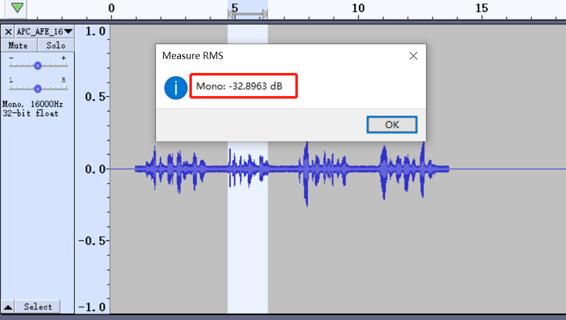
If we want to pull up this signal, adjust the slope of the AGC curve. From the average amplitude of the above figure, it is known that the signal is in section -40dB~-20dB. The easiest way is to increase the slope. This is equivalent to pulling the signal of -40dB~-20dB to -20dB to -5dB.
s16Compression_ratio_input(MI)/compression_ratio_input[(AGC)[AGC_CR_NUM] = {-80,-60,-40,-20,0};

s16Compression_ratio_output(MI)/compression_ratio_output[(AGC)[AGC_CR_NUM] = {-80,-40,-20,-5,-5};
6. Audio player and hardware selection
6.1. Speaker And Microphone Selection Suggestions
-
The microphone sensitivity is best below -35dB, but it is not recommended to be too small, otherwise it will not meet the requirements of the distance.
-
Select a speaker with case.
6.2. Structural Design Suggestion
-
The best distance between Microphone and speaker is 4~10cm, in this range, the longer the distance, the better the effect.
-
It is forbidden to use a speaker without a case. The tight connection around the case helps reduce the sound transmission from the rear to the front of the speaker.
-
The speaker case must be firmly fixed in the cavity to prevent the speaker from generating clicks.
-
When the speaker is installed inside, high-density foam rubber (anti-vibration, sound insulation) can be used to make the speaker more firm.
-
The opening of the sound position must be at least 20% of the speaker area, and the distance from the speaker is 1~2mm.
-
Foam rubber can be added to the back of the microphone to reduce the direct coupling with the speaker. It is easier to pack the microphone and foam rubber into one case.
-
Microphone must be aligned with the opening on the case.
7. Basic debugging process
The following describes the general debugging process, the parameters have no reference significance.
-
Confirm the gain of AO
According to the section Confirm The Gain Of Speaker, play TestFile1 and TestFile2 with demo, choose a large gain according to requirements.
No requirements are given here, so we decide 0dB as the gain.
-
Confirm the gain of AI
Use the initial gain selected above and follow the introduction in Confirm The Gain Of Microphone, place the decibel meter and the device together, where a player is one meter away from , use the player to play TestFile1, and adjust the gain to make the decibel meter reaches 70dbA.Adjust the gain of the microphone step by step to make the incoming sound loud enough, preferably to -25DBRMS. Because the mic sensitivity of the model used is relatively low, the mic gain is set to 54dB to barely reach close to -25DBMS.
-
Test the internal sound insulation of the structure
Use the initial gain selected above and follow the introduction in Internal Isolation, test the sound insulation effect inside. Record and broadcast TestFile1 to get the average RMS amplitude, record it as AVGRMS1, block the mic hole, repeat the operation, record as AVGRMS2, internal sound insulation= AVGRMS1 - AVGRMS2.

Figure7-1 internal sound insulation AVGRMS1

Figure7-2 internal sound insulation AVGRMS2
AVGRMS1 - AVGRMS2 = -16.2206db - (-24.214db) > 6, the internal sound insulation effect meets the requirements.
-
Test the echo return loss of structure
Follow the introduction in Echo Return Loss, and test the effect of it. Record the average RMS amplitude of TestFile1 as AVGRMS1, record and broadcast TestFile1 and record the average RMS amplitude as AVGRMS2.

Figure7-3 echo return loss AVGRMS1

Figure7-4 echo return loss AVGRMS2
The structure of the device is poorly designed, and there is almost no loss of echo.
-
Adjust the gain of AI and AO
Adjust the gain of AI and AO slightly to record and broadcast the TestFile2 without distortion. If it still exists, adjust the gain to be undistorted by reducing the gain of the microphone and speaker (except distorted while broadcasting by speaker).

As shown above, the waveform has been clipped, adjust the gain of the microphone and speaker to solve. Test with a decibel meter at one meter away and found that when the speaker plays TestFile2, it has reached about 75dBA, which is already relatively large. Adjust the speaker gain until the decibel meter displays about 65dBA. After that, it is confirmed the microphone's gain is 48dB and speaker's is -9dB.
-
Sweep the speaker and correct EQ
First of all, based on the gain confirmed above, record and broadcast the sweep audio file TestFile3. Create a dual-channel file, place the recording on the left, and place the raw sweeping on the right, aligning the two. Import the recorded data and the original audio file played; adjust them to ensure that the data is aligned on the time axis.

Click Frequency Analysis and set the corresponding parameters to get the frequency response characteristics.

Obtain the curve, copy it to Excel, and calculate the EQ table of AO.
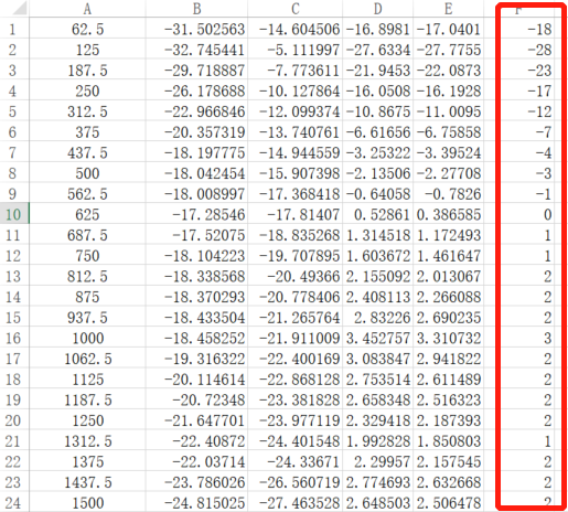
Fill it in EQ table of AO.
-
Adjust the AEC parameter
First, we fill in the initialization parameters of AEC, set environment variables, and perform single talk test, record and broadcast TestFile2, find the relevant audio of AEC. It can be seen from the audio file of AecOut that only the bands marked in red are not eliminated. The green mark indicates that the AEC algorithm has not yet converged which is out of consideration. Then adjust the AEC parameters to compare the AEC intensity of these two frequency bands.

The AecOut after adjusted is as follow:

In the debugging process, even if the intensity of AEC is adjusted to the maximum, the echo of the corresponding part cannot be eliminated. Adjust the parameters until the microphone is still louder but the echo is smaller, and then use EQ to eliminate it.
-
Adjust AI NR parameter
Fill in the default parameters, and make fine adjustments when it is found that the noise reduction effect is not ideal due to factors such as the circuit and the test environment.
eMode:E_MI_AUDIO_ALGORITHM_MODE_MUSIC

u32NrIntensity:20

u32NrSmoothLevel:10

eNrSpeed:E_MI_AUDIO_NR_SPEED_MID
-
Adjust AI EQ parameter
Except for certain situations, it is not recommended to directly use AI EQ to adjust the gain.
-
Adjust AI AGC parameter
Fill in the initial parameters first and then fine-tune. The initial parameters are as follows:
compression_ratio_input[AGC_CR_NUM] = {-80,-60,-40,-20,0};
compression_ratio_output[AGC_CR_NUM] = {-80,-40,-20,-10,-5};
user_mode = 1;
gain_max  = 30;
gain_min  = 0;
gain_init = 0;
drop_gain_max = 36;
attack_time = 1;
release_time = 3;
noise_gate_db = -60;
noise_gate_attenuation_db = 0;
target_level_db = -5;
Then analyze the audio files processed by AEC.
Select a few segments and check their average DBRMS.
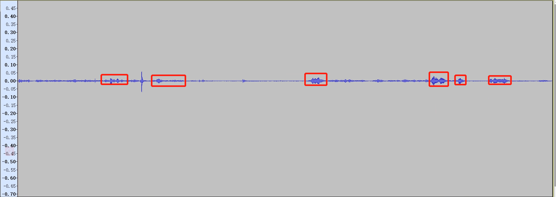
Then change the output in the default parameter curve and adjust it to the required dB. The adjustments are as follows:

The sudden height is caused by speaker distortion, and the echo that appears suddenly and cannot be eliminated is pulled up by the AGC. There is no other way except to change the structure of the speaker.
8. Common Case
-
Power amplifier circuit distortion
The case of power amplifier circuit distortion is mainly about how to make sure the problem on circuit and how to solve it.
When we get the device and perform a preliminary frequency sweep analysis(set the gain of mic and speaker to 0dB, self-broadcast and self-recorded sweep file). If the frequency response characteristic is very poor, almost all frequency bands have resonance, and it is relatively high, it is necessary to suspect that the power amplifier circuit has appeared very serious distortion in the current state.
On the premise that there is no problem with the mic frequency response characteristics, the test can be performed by replacing the speaker. After replacing several speakers, the contrast audio file is not greatly improved. Ask hardware engineer to measure the input and output signals of the power amplifier circuit.
If the gain of speaker has been attenuated relatively large, the input signal amplitude of the power amplifier is small, but the output signal is still distorted, it is necessary to confirm whether the amplifier magnification is too large, or the power supply voltage is too small to meet the needs of amplification, resulting in peak clipping. It is best to solve by modifying the power amplifier circuit.
If it has been mass-produced, the hardware modification has too much influences or difficulties, we can only try to increase the signal amplitude of the intercom without distortion to make up for the defect of low sound.
First, ask hardware engineer to help measure how much the speaker gain can be reduced to ensure that the output signal of the power amplifier circuit is not distorted when playing the sweep file. Used the value as the software adjustable maximum gain.
In order to make the speaker output large enough, use AO AGC to enlarge the output data as much as possible (limited to -3~-1dB, leaving a margin to avoid distortion of the power amplifier).
-
Handling of popping from speaker raw data
During the intercom, it is found that the data to be played (that is, the original data transmitted from the far end) will often burst. Use multi-point averaging on the data to pull down some burst points. (That is, the value of the current sampling point is averaged with the previous points, how many points are averaged once, please adjust according to the specific situation, the more serious the explosion, the more points are required)
Calculation formula:
y=\frac{x(n)}{n}+\frac{x(n-1)}{n}+\frac{x(n-2)}{n}+...+\frac{x(0)}{n}It is equivalent to doing a low-pass filter, which can effectively eliminate the sawtooth wave. The side effect is that high-frequency signals with short periods will be filtered out. The multi-point averaging method will blur the sound quality and is not recommended for other situations.
-
The noise in voice broadcasted by the other side speaker is suppressed after pulled up
When the noise of the broadcasted voice fluctuates from time to time, it is first necessary to confirm which party is the cause. Dump the AI's VqeIn and VqeOut to confirm it.
Use adobe audition to listen to whether VqeOut has this phenomenon. It not, it is to be solved by the other side. If it is in VqeOut but not in VqeIn, it is basically due to the processing of Vqe. The possible reasons are as follows:
-
The short voice interval results in slow NR convergence.
Solutions:
Enhance the convergence speed of NR, eNrSpeed = E_MI_AUDIO_NR_SPEED_HIGH.
Enable the comfort noise of AEC, bComfortNoiseEnable = TRUE.
-
Improper EQ adjustment.
If it is seen from VqeOut that the noise is in a fixed frequency band, the EQ of the corresponding frequency band can be adjusted to cover the noise.
If the VqeIn sounds fluctuate from time to time, dump the file of Aec and compare the AecAiIn and AecOut audio files to confirm whether it is produced by the Aec process or the sound in the environment. If it is AecOut, it is confirmed to be caused by incomplete AEC elimination. Check the frequency band of the "noise" (echo), and increase the intensity of the elimination to eliminate it.
Solution: Adjust u32AecSupfreq and u32AecSupIntensity of AEC.
-
-
Our speaker has a "tail tone".
First, dump the VqeIn audio file of AO for analyzing. If the VqeIn data already has "tail", it is caused by the incomplete AEC elimination of the other side. The processing method is as follows:
-
Adjust the AEC parameters of the other side.
-
If the frequency band of “tail tone” is relatively fixed, adjust EQ to delete it.
-
If the "tail" frequency band is not fixed, when the "tail" and the normal voice are quite different, it can be processed by AGC(Only suitable for fixed models, and will not accidentally damage the normal voice signal). Refer the section How to check the signal value to analyze the tail signal, and then adjust the ACG curve(s16Compression_ratio_input and s16Compression_ratio_output), or use the noise threshold to cover the "tail"(s32NoiseGateDb和u32NoiseGateAttenuationDb).
-
-
The other side didn`t complete elimination echo in one-way intercom
We can hear the echo because the other side has not eliminated it completely. The general reasons are as follows:
-
The speaker or mic gain of the other side is too much.
Solution: reduce the speaker or mic gain of the other side and reduce the mic gain of us.
-
The other side has a poor structure and serious internal crosstalk.
Confirmation method:
-
Use clay to block the pickup hole and speak, if the sound can be heard, the air tightness of the structure is poor.
-
Use clay to completely block the back of the mic and talk in our side, if the echo is greatly improved, it means that there is a structure problem with the other side.
Solution: suggest the other side to adjust the structure
-
-
Inappropriate AEC intensity adjustment of other side.
Solution: suggest the other side to adjust the intensity.
Note:
-
If the frequency band of echo sent back other side is fixed and sample, we can delete it through the EQ of AO;
-
Or the frequency band is not fixed, but it is quite different from the normal voice, which can be covered by the AGC curve of AO (s16Compression_ratio_input and s16Compression_ratio_output) or the noise threshold (s32NoiseGateDb and u32NoiseGateAttenuationDb). Only applicable when only one device is paired, and the normal voice signal may be damaged by mistake.
-
-
-
We didn`t complete elimination echo in one-way intercom
The cause and solution are similar to the above.
-
The heavy gain of mic/speaker causing the sound to burst.
Solution: reduce the speaker or mic gain of us and reduce the mic gain of other side.
-
We have a poor structure and serious internal crosstalk.
Confirmation method:
-
Use clay to block the pickup hole and speak, if the sound can be heard, the air tightness of the structure is poor.
-
Use clay to completely block the back of the mic and talk in the other side, if the echo is greatly improved, it means that there is a structure problem.
Solution: Adjust the structure
-
-
Inappropriate AEC intensity adjustment of us.
Analyzing AecAiIn, AecAoIn and AecOut to confirm where are the left echo in, and then adjust parameters and eliminate intensity.
Note:
-
After processing by our AEC, there is still echo with fixed and sample frequency band, we can delete it through the EQ of AI;
-
Or the frequency band is not fixed, but it is quite different from the normal voice, which can be covered by the AGC curve of AI(s16Compression_ratio_input and s16Compression_ratio_output) or the noise threshold (s32NoiseGateDb and u32NoiseGateAttenuationDb). Only applicable when only one device is paired, and the normal voice signal may be damaged by mistake.
-
-
-
The sound heard by other side fluctuates from time to time in two-way intercom.
Confirm the problem caused by which side first through dumping the AI`s AEC and VQE of our sied to analyze the VqeOut. If there is no problem, the cause is from the other side, which should be solve. On the contrary, we need to check through the following factors:
-
The echo from the other side was too loud, causing too many mic signals to be eliminated by our AEC.
Solution:
Adjust the AEC and analyze AecAiIn, AecAoIn and AecOut to confirm which frequency band is too heavy.
Re-adjust the AEC frequency band and elimination intensity(u32AecSupfreq and u32AecSupIntensity), or reduce the speaker`s gain.
-
Mic terminal enabled the AGC without incorrect parameter.
Confirmation method:
Try to disable it to check whether the situation is getting better.
Solution:
Adjust AGC parameters in combination with audio files, pay attention to the setting of curve (s16Compression_ratio_input and s16Compression_ratio_output), noise threshold(s32NoiseGateDb and u32NoiseGateAttenuationDb) and u32DropGainMax.
-
-
The sound heard by us fluctuates from time to time in two-way intercom.
Confirm the problem caused by which side first through dumping AO`s VqeIn and VqeOut of our side. It is caused by the other side if the problem has already exist in VqeIn. On the contrary, we need to check through the followings:
-
Speaker terminal enabled the AGC without incorrect parameter.
Confirmation method:
Try to disable it to check whether the situation is getting better.
Solution:
Adjust AGC parameters in combination with audio files, pay attention to the setting of curve (s16Compression_ratio_input and s16Compression_ratio_output), noise threshold(s32NoiseGateDb and u32NoiseGateAttenuationDb) and u32DropGainMax.
-
Caused by structure, speakers, etc.
For example, if the speaker is not installed properly, some frequency bands of the speaker cannot be played.
-
-
Speak simultaneously will exist words missing
The reasons are as follows:
-
The side lacked of words had heavy AEC intensity.
-
Incomplete echo elimination of one side, causing the AEC of the other side to delete the voice signal by mistake
-
Too much mic/speaker gain affects the AEC processing result
-
Inappropriate parameter setting of EQ/AGC
-
-
Speaker breaks, vibrato
-
Structure or speaker problem
-
Reduce our speake`s gain or the mic`s gain of other side
-
-
Inappropriate AEC parameter setting
-
Problem
As shown below, the audio files are AecAoIn and AecOut. The audio file output by the AEC algorithm still has some echo remaining, which is caused by the low AEC intensity setting.

-
Solution
Increase AEC intensity.
-
-
Speaker distortion causes incomplete AEC
-
Problem
As shown below, the audio files are AecAiIn, AecAoIn and AecOut. Speaker distortion makes AecAiIn to have a frequency band, which AecAoIn does not have (the marked part in the figure), which causes the AEC algorithm to fail to obtain the correct reference signal and makes the AEC algorithm incompletely eliminated. The frequency band where the echo exists is exactly the frequency band produced by the speaker distortion.
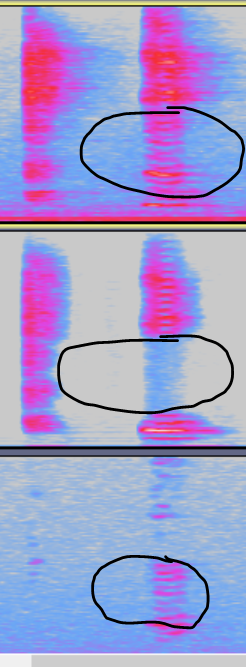
-
Solution
-
Change speaker
-
Reduce the gain of Ao
-
-
-
Circuit caused noise
-
Problem
As shown below, the obvious regular noise is generally caused by the circuit.

-
Solution
Ask the HW engineer to troubleshoot the circuit cause.
-
9. Note
After the speaker gain is fixed, play a 1KHz 0dB sine wave file or sweep file according to the current gain, TestFile3. To prevent the speaker from burning out, ask the hardware engineer to help measure the peak-to-peak value of the signal sent to the speaker. According to the impedance of the speaker, calculate whether it exceeds the rated power under this gain.